Another development cycle is coming to an end. Bruno released libpano13 2.9.17 and paved the way for Hugin 2010.2.0. This version of Hugin will bring a lot of new features, amongst others a versatile masking tool and finer grained control of the control point (CP) detection process, courtesy of Thomas Modes. Good news for Windows user as well: galvanized by Emanuele Panz and his new NSIS based installer that solves the issues with distribution of patented software, also the Windows users community is on the forefront this time.
Time to do some cool stuff with Hugin: mosaics. The basic functionality for mosaics has been in the repository for about a year, and it has matured well. This morning I set out to shoot and stitch a mosaic.
Stitched mosaics differ from traditional stitched panorama in two major ways:
- In an ideal mosaic, all images depict a single, perfectly flat subject.
- The images are taken from different points of view.
Mosaics present a few challenges of their own. Think of them as protrusions and intrusions from/into the perfectly flat imaginary plane that you are trying to shoot.
Shooting
Not much is flat in the real world. If parallax prevented seamless concordance in a traditional stitched panorama, depth and perspective prevent seamless concordance in a mosaic. While parallax can be almost completely eliminated with accurate camera positioning on the no-parallax point, perspective is a given and will be with us throughout the process and into the finished product. You need to be aware of it while shooting a mosaic more than you need to be aware of moving objects when shooting a stitched panorama. The tools to deal with it are the same: overlap (plenty!); masking; and, inevitable in this case, retouching/editing.
For this kind of shooting, I first walk parallel to the subject watching how protrusions and intrusions move relative to the imaginary ideal plane as I move along. I look for vertical (not necessarily straight) lines in the plane that could act as stitching seams, i.e. will be unencumbered by protrusions in two adjacent shots. If I can’t find such a virtual seam line I will have a hard time masking and retouching the seam. In a second pass I shoot images straight at the subject, one between every pair of the still virtual seam lines, with a lot of overlap. In a third pass, I take pictures at different angles to “get around” protrusions such as trees that hide areas of interest of the subject.
All images were shot hand held. Like for traditional panoramas, constant exposure and color are important.
Order
I found that order matters. I get best results when starting from an anchor image in the middle of the mosaic and working my way to the edges. To simplify the work flow, once the images are loaded I re-order them in the Images tab, making sure the anchor image is the top one.
Setting the Stage
Start a recent version of Hugin. You will be switching forth and back between the main window and the fast preview window, so if you have two displays, open them side by side. Unlike Terry Duell’s suggestions I found that it is not necessary to add images individually to the project, but a little bit of pre-planning is necessary. There will be some inevitable forth and back as this is an iterative process.
Generate Control Points
Bad news first: you most likely will have to enter CPs by hand. That said, it’s easy.
It is paramount that all CPs are on the same plane and no currently existing CP detector known to me meets the condition. Even small depth errors (e.g. relief on a wall) has big impact. Avoid CPs between non-contiguous images. Three or four well distributed (i.e. not on a straight line) CPs are enough. If vertical lines are present, add one vertical CPs on each image that has them. Conceptually, the three corners of a triangle in space are enough to define a plane and you are looking to define the common plane between two images.
Start with a Calibrated Lens
I found mosaics optimization to be much more sensible to the starting parameters than spherical optimization; and the outcome to be much more sensible to lens distortion than traditional panoramas. Get lens distortion out of the way before starting. If you have saved calibration data for your lens load it now. Else, here’s a quick fix.
In the Fast Preview window:
- Hide all images but one with plenty of lines that should be straight in the real world.
- Select rectilinear projection.
- Center the preview on the visible image and zoom in on it with the field of view (FoV) sliders.
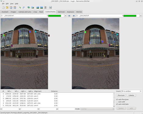
Your goal is to make straight lines look straight, and the Fast Preview window will give you valuable visible feedback. In the Control Points tab, set a few line CPs:
- Select the visible image into both the left and right panes and start adding CPs on lines.
- For vertical lines, click on one end of a vertical line in the left pane and on the other end in the right pane.
- For all other lines do the same, but check that the CP-type drop down says “another line” and the table says “line” and a number. The name of horizontal CPs is misleading. Horizontal lines are to identify the horizon itself, not lines parallel to it.
With six well distributed lines you can already get a good approximation. In the Optimizer tab:
- Select to optimize “the custom parameter below”
- Select “only use control points from images visible in the preview window”
- Deselect all parameters
- Select only Pitch and Roll of the above image
- Run a first optimization (and adjust the view in the Fast Preview window if necessary)
- Deselect all parameters
- Select Barrel
- Run a second optimization
- Select Pitch, Roll and Barrel and optimize them all
- Now deselect Barrel, and leave the lens parameters alone
There is more to proper lens calibration, but this should be enough approximation for the project at hand. Confirm visually that the lines are straight in the Fast Preview window before continuing.
Start from the Center
Start with only your anchor/calibration image visible in the middle of the Fast Preview (in rectilinear projection) and all other images hidden.
In the Optimizer tab:
- Select to optimize “the custom parameter below”
- Select “only use control points from images visible in the preview window”
- Optimize for Pitch and Roll of the anchor image. Make sure it’s X/Y/Z parameters are 0 (in the Images tab).
Optimize Image after Image
Repeat the following for each image, always verifying the visual result in the Fast Preview after each optimization.
In the Fast Preview window:
- Visually check that the current result is approximately OK
- Adjust the FoV sliders if necessary
- Make the next image visible
In the Images tab:
- Select the image that just became visible in the Fast Preview window
- Edit it’s X value. Enter a negative value if it is to the left or a positive one if it is to the right. Over time you will get a feel for the magnitude. Start with +/-1. Make sure it is roughly positioned where it belongs, slightly more to the outside than to the inside.
In the Optimizer tab
- Select to optimize “the custom parameter below”
- Select “only use control points from images visible in the preview window”
- Optimize for Yaw, Pitch, Roll, X, Y, Z of the newly visible image
Repeat for all images. At the end do one more optimization run, optimizing Yaw, Pitch, Roll, X, Y, Z for all images but the anchor image, and only Pitch and Roll for the anchor image.
 Improve Slowly
This is a step by step, image by image process. And we’re not finished yet. You may find that the project needs further tweaking. It’s not an issue of mathematical precision but rather one of controlling the position and warping in critical areas where the different perspectives from the different pictures collide.
Terry suggested dragging the image in the Fast Preview window instead of the above step in the Images Tab. And indeed the Fast Preview has a Move/Drag tab with mosaic mode. Unfortunately dragging an image will automatically drag all other images connected by CPs, so unless you do this only once before adding CPs, dragging won’t work. I found the way through the numeric input in the Images tab to be preferable. It enabled me to go back and rework the positioning of individual images without losing the work done on CPs.
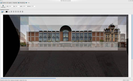
 Move/drag in the Fast Preview window is useful associated with cropping functionality. I use manual cropping in this case, it’s fast and intuitive. When the mosaic looks good in the Fast Preview window, head to the Stitcher tab and render it. Make sure to output both the blended panorama and all remapped images by checking the appropriate check boxes. Hit the Stitch Now button, enter a prefix and go get a deserved break while the computer churns away.
Masking
Hugin has a built in masking tool. Masking in the input images is more useful for panoramas than for mosaic, because in a well shot panoramas it is reasonable to assume that the images align naturally and the masking is only needed to exclude / include details. With mosaics, the assumption is wrong, and I prefer to do masking in output images, already warped and aligned, together with editing and some other unspecified fiddling to achieve a visually pleasant result.
Post Processing
Below is a scaled rendering of the blended mosaic. No post-processing applied yet. The original is about 21.000 pixels wide. It’s not bad, but “perspective collisions” are visible at the seams and will require retouching. It’s time to prepare the project for your favorite image editor.
 Copy all the rendered images into a single TIFF file. On the command line, enter:
$ tiffcp prefix* layeredmosaic.tif
Open the resulting file with Gimp. The layers will be perfectly aligned. Add mask layers to them and start editing, or export to a Photoshop file if you are more comfortable with that image editor. My Photoshop CS 2 (quite old, but still does the job) is not able to open properly the multi-page TIFF file.
Improvements
This was a quick proof of concept / tutorial. If I was to do something serious with this image, I would probably re-shoot it, taking advantage of the building regularity and adding more images, one in between every pair of columns.
Conclusion
Reaching this advanced stage in the image creation process was relatively easy with Hugin. Now, depending on your level of perfectionism and intended purposes, there are still hours of editing ahead before the file can be declared good to print. I don’t have enough wall space available for this 3.5m / 11 feet long mosaic. If you have and are interested in this or similar commissioned work, I’d like to hear from you.
Filed under: hugin, libpano, tutorial | Tagged: Bruno Postle, Emanuele Panz, Terry Duell, Thomas Modes | 2 Comments »


